


By Alon Davidy, Heat Transfer Researcher
In the Fluid Catalytic Cracking process, the regenerator is responsible for burning off the coke that has accumulated on the catalyst particles during the cracking reaction. To control the temperature in the regenerator and ensure efficient coke combustion, various cooling methods are employed. There are some common methods used to cool the FCC regenerator, as follows:
Air/Oxygen introduction: Air or oxygen is introduced into the regenerator to support the combustion process. This helps to burn off the coke and generate heat. The flow rate of air or oxygen can be adjusted to control the temperature and ensure efficient coke combustion.
Steam or water injection: Steam or water can be injected into the regenerator as a method of cooling. This is achieved by evaporating the injected water or steam, which absorbs heat from the regenerator and reduces the temperature. The injected steam or water can also help to dilute the flue gas and control the oxygen concentration, aiding in the combustion process.
Internal refractory lining: The regenerator vessel is often lined with refractory materials, which have high heat resistance. These refractory linings help to minimize heat transfer to the vessel shell, reducing the overall temperature. They also protect the vessel from excessive heat and prolong its lifespan.
Catalyst cooler: The FCC catalyst cooler helps to regulate the regenerator temperature and ensures the continuous and efficient operation of the fluid catalytic cracking process in petroleum refineries. The catalyst cooler is basically a vertical shell-and-tube heat exchanger attached to the regenerator. The cooler extracts high quality heat from the catalyst in the regenerator to produce high pressure steam. The hot catalyst enters the cooler at a high temperature, and as it passes through the heat exchangers, it comes into contact with a cooling medium, such as air or water, which absorbs the excess heat and lowers the catalyst’s temperature. The cooled catalyst is then directed back into the FCC reactor to continue the cracking process.
Catalyst Withdrawal: Some FCC units utilize a catalyst (such as zeolite) withdrawal system that removes a portion of the catalyst from the regenerator before it reaches excessively high temperatures. This helps to control increases in temperature and it prevents damage to the catalyst.
These cooling methods are implemented in combination or individually, depending on the specific design of the FCC unit and the requirements of the refinery. The aim is to maintain optimal operating conditions, maximize coke combustion efficiency, and ensure the long-term integrity of the regenerator equipment. The cooling of the regenerator’s surface can be achieved by impinging water droplets (spray), ejected from a spray nozzle. Spray cooling can provide uniform cooling and it can handle high heat fluxes in both a single phase and two phases. Figure 1 shows the regenerator shell cooling mechanism [1].

Figure 1: Regenerator cladding spray cooling mechanism [1].
Water spray cooling can be achieved through various methods, including:
Direct Spray Cooling: In this method, water is sprayed directly onto the surface that needs to be cooled. The water droplets come into direct contact with the hot surface, and evaporation takes place, resulting in cooling.
Indirect Spray Cooling: In indirect spray cooling, water is sprayed into the surrounding environment or onto a medium, such as a heat exchanger or cooling coil. The hot air or fluid passing through the medium comes in contact with the sprayed water, and heat transfer occurs through evaporation.
Water spray cooling offers several advantages:
1) Efficient Heat Transfer: Evaporative cooling through water spray can effectively transfer large amounts of heat due to the high latent heat of vaporization of water.
2) Cost-Effective: Water is readily available and relatively inexpensive compared to other cooling methods.
3) Environmental Benefits: Water spray cooling is considered environmentally friendly as it does not require the use of refrigerants or other chemicals that may be harmful to the environment.
4) Flexibility: Water spray cooling can be easily applied to various surfaces and systems, making it a versatile cooling technique.
However, there are also some considerations when using water spray cooling:
1) Water Consumption: It is essential to manage water usage and avoid excessive waste when employing water spray cooling systems.
2) Corrosion and Scaling: Depending on the quality of the water and the materials in-volved, there may be a risk of corrosion or scaling on the cooled surfaces or equipment.
3) Maintenance: Water spray systems require regular maintenance to ensure proper functioning, including cleaning nozzles, checking for blockages, and monitoring water quality.
This research provides thermal hydraulic design of regenerator spray cooling systems. In the framework of this research, Fire Dynamics Simulator (FDS) software has been applied in order to simulate the temperature field and the water vapor mass fraction. The numerical simulations have been carried out for two cases. The first case has been carried out for a distance of 0.5 m between the nozzle injector and regenerator cladding wall, and the second case has been carried out for a distance of 0.2 m. Grid sensitivity study has been carried out on the FDS model. Numerical integrations have been carried out over the time, in order to calculate the average temperatures. The difference between these four average temperatures calculated by applying different grids is less than 7.4%. The calculated temperatures obtained by FDS software, have been validated against COMSOL numerical results and the previous research works. In the framework of this research a thermal model has been developed in COMSOL multi-physics software. It has been assumed that the heat transfer convective coefficient is 20,000 [W/(m2 K)]. This value is very similar to the convective coefficient obtained by previous empirical correlation. Figure 2 shows the calculated temperature field for the second case (the mesh size of the spray cooling system contains 64,000 cells).
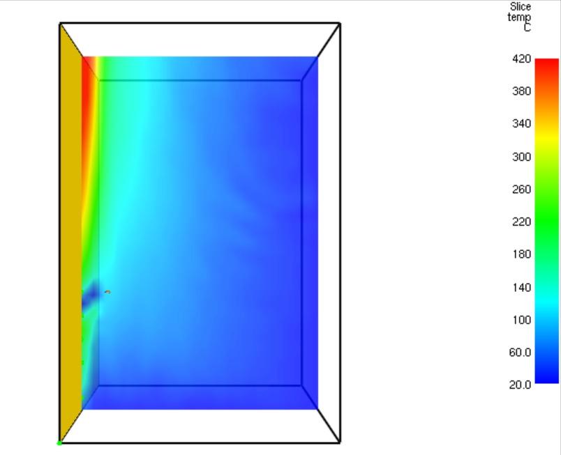
Figure 2: Temperature distribution profile (°C) of the water vapor gases near the wall at t = 600 s (the mesh size of the spray cooling system contains 64,000 cells).
Figure 3 provides the transient thermal response of the five thermocouples (TC1- TC5).
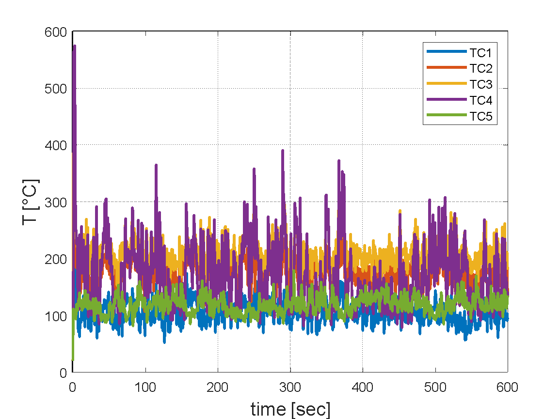
Figure 3: Transient thermal response of the five thermocouples (TC1- TC5).
From figure 3 it can be seen that there is a decrease in the calculated temperatures for the second case. The water spray system manages to cool the steel wall more effectively as the water spray system approaches the steel cladding. The thermocouple TC5 is cooled off by the direct water impingement. Figure 4 shows the transient response of the water vapor mass fraction obtained by the five sensors.
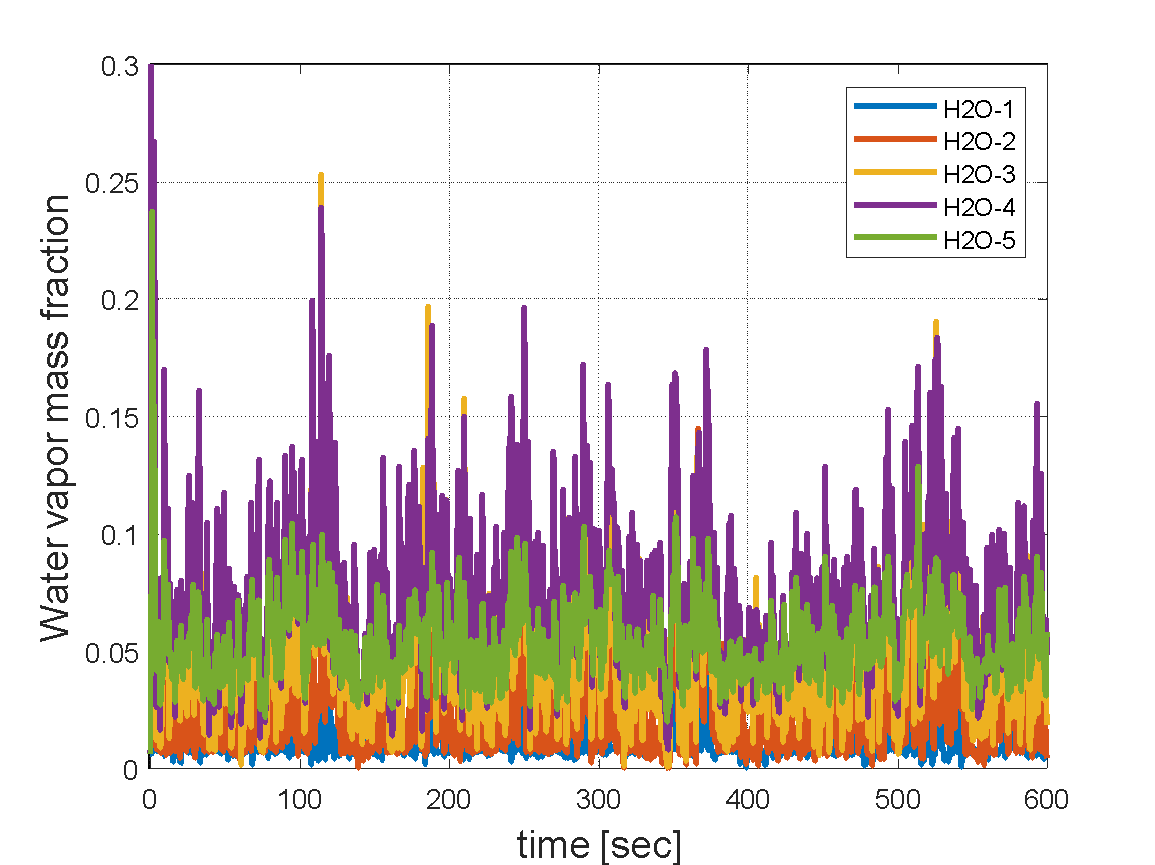
Figure 4: Transient response of the water vapor mass fraction sensors (H2O1- H2O5).
It can be seen from figure 4, that the vapor mass fraction readings of sensor no. 4 and 5 are larger than the other three water vapor mass fractions. This physical phenomenon is caused by significant water evaporation. The water evaporation is very significant at relatively short times. According to figure 3, at shorter times the surface temperatures are greater than the atmospheric water boiling temperature.
More information is available in the following paper:
[1] Davidy, A. Thermal Hydraulics Simulation of a Water Spray System for a Cooling Fluid Catalytic Cracking (FCC) Regenerator. Dynamics 2023, 3, 737-749. https://doi.org/10.3390/dynamics3040039.
Connect with Alon Davidy on Linkedin.
Note: The views, thoughts, and opinions expressed in the content above belong solely to the author and do not necessarily reflect the opinions and beliefs of Refining Community or its parent company, CRU Group.
Hi, nice post. I noticed that there is a problem with your website in Internet Explorer. Since IE is still the most popular browser, a lot of people will miss your amazing writing because of this issue.