By: Dr. Marcio Wagner da Silva, MBA, Transfer and Stockpiling Manager at Petrobras
Introduction and Context
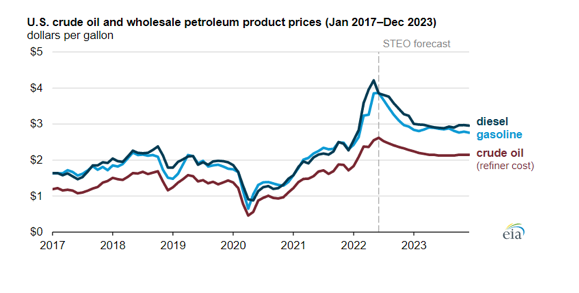
Nowadays, the capacity to add value to the bottom barrel streams represents great competitive advantage among refiners. This is true especially considering the stricter regulations like the IMO 2020 that imposes significant reduction in sulfur content of marine fuel oils (BUNKER). These regulations require even more capacity to treat bottom barrel streams, especially to refiners processing heavier crude oils who are put under pressure by refining margins that are still in post-pandemic recovery, as exemplified for the USA market in Figure 1.
Under this scenario, bottom barrel process units that are able to improve the quality of crude oil residue streams (Vacuum residue, Gas oils, etc.) or convert them to higher added value products gain strategic importance, mainly in countries that have large heavy crude oil reserves. These process units are fundamental for compliance with environmental and quality regulations, as well as to ensure profitability and competitiveness of refiners by raising refining margins. In a most recent trend, the reduction in transportation fuels demand is leading the refiners to look for closer integration with petrochemical assets, creating a necessity to maximize the yield of petrochemicals in the refining hardware. The use of residue upgrading technologies to produce petrochemicals against transportation fuels can be an attractive route in some markets.
Available technologies to processing bottom barrel streams involve processes that aim to raise the H/C relation in the molecule, either through reducing the carbon quantity (processes based on carbon rejection) or through hydrogen addition. Technologies that involve hydrogen addition encompass hydrotreating and hydrocracking processes while technologies based on carbon rejection refers to thermal cracking processes like Visbreaking, Delayed Coking and Fluid Coking; catalytic cracking processes like Fluid Catalytic Cracking (FCC); and physical separation processes like Solvent Deasphalting units. Some refining schemes can apply the synergy between residue upgrading technologies aiming to ensure higher added value to the processed crude oils as well as meet the regulations and ensure higher refining margins in the downstream sector. An interesting case is the combination of Hydrocracking and Fluid Catalytic Cracking Technologies– normally these technologies are faced as competing technologies due to the feed streams that are processed, but in some cases the synergy between the hydrocracking and FCC technologies can ensure high bottom barrel conversion capacity and profitability, despite the relatively high capital investment.
Fluid Catalytic Cracking Technologies – Carbon Rejection Route
The installation of catalytic cracking units allows the refiners to process heavier crude oils at a cheaper cost, thereby raising the refining margin, mainly in higher crude oil prices scenario or in geopolitics crises that can become difficult the access to light oils. The typical Catalytic Cracking Unit feedstream is gas oils from vacuum distillation process. However, some variations are found in some refineries, like sending heavy coke naphtha, coke gas oils and deasphalted oils from deasphalting units to processing in the FCC unit.
In a conventional scheme, the catalyst regeneration process consists in the carbon partial burning deposited over the catalyst, according to chemical reaction below:
C + ½ O2 → CO
The carbon monoxide is burned in a boiler capable of generating higher pressure steam that supplies other process units in the refinery. Figure 2 presents a process scheme for a typical Fluid Catalytic Cracking Unit (FCCU).
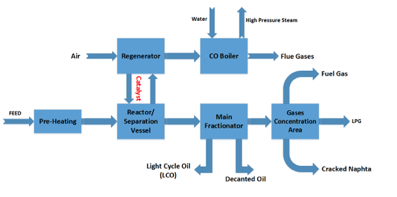
The principal operational variables in a fluid catalytic cracking unit are reaction temperature, normally considered the temperature in the top of the reactor (called riser), feed stream temperature, feed stream quality (mainly carbon residue), feed stream flow rate and catalyst quality. Feedstock quality is especially relevant, but this variable is a function of the crude oil processed by the refinery.
An important variation of the fluid catalytic cracking technology is the residue fluid catalytic cracking unit (RFCC). In this case, the feedstock to the process is basically residue from atmospheric distillation column, due to the high carbon residue and contaminants (metals, sulphur, nitrogen, etc.) are necessary some adaptations in the unit like catalyst with higher resistance to metals and nitrogen and catalyst coolers. Furthermore, it’s necessary to apply materials with the most noble metallurgy due the higher temperatures reached in the catalyst regeneration step (due the higher coke quantity deposited on the catalyst). That significantly raises the capital investment to the unit installation. Nitrogen is a strong contaminant to the FCC catalyst because it neutralizes the acid sites of the catalyst which are responsible for the cracking reactions.
When the residue has high contaminants content, it is common with the feed stream treatment in hydrotreating units to reduce the metals and heteroatoms concentration to protect the FCC catalyst. Typically, the average yield in fluid catalytic cracking units is 55% in volume in cracked naphtha and 30 % in LPG.
Usually, catalytic cracking units are optimized to aim the production of fuels (mainly gasoline), however, some process units are optimized to maximize the light olefins production (propylene and ethylene). Process units dedicated for this purpose have their project and operational conditions significantly changed once the process severity is strongly raised in this case.
The reaction temperature reaches 600 oC and higher catalyst circulation rate raises the gases production, which requires a scaling up of the gas separation section.
Over the last few decades, the fluid catalytic cracking technology was intensively studied aimed at the development of units capable of producing light olefins (Deep Catalytic Cracking) and to process heavier feedstocks. The main licensors for fluid catalytic cracking technology nowadays are the companies KBR, UOP, Stone & Webster, Axens, and Lummus Company.
Despite the great operational flexibility which fluid catalytic cracking technology has given to the refineries, some new projects have dismissed these units in the refining scheme, mainly when the new refinery objective is to maximize middle distillates products (Diesel and Kerosene).
Improving the Yield of Petrochemicals in the Refining Hardware – The Petrochemical FCC Technologies
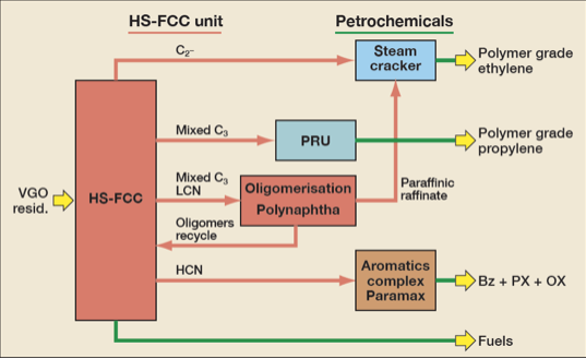
As quoted earlier, in markets with high demand by petrochemicals, the petrochemical FCC can be an attractive alternative to refiners aiming to ensure higher added value to bottom barrel streams. An example of FCC technology developed to maximize the production of petrochemical intermediates is the PetroFCC™ process by UOP Company. This process combines petrochemical FCC and separation processes optimized to produce raw materials to the petrochemical process plants, as presented in Figure 3. Other available technologies are the HS-FCC™ process commercialized by Axens Company, and the INDMAX™ process licensed by Lummus Company. The basic process flow diagram for HS-FCC™ technology is presented in Figure 4.
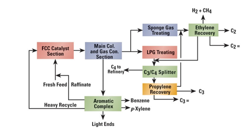
It’s important to consider that both technologies presented in Figures 3 and 4 are based on Petrochemical FCC units that have special design considerations due to the most severe operating conditions.
To petrochemical FCC units, the reaction temperature reaches 600 oC and higher catalyst circulation rate raises the gases production, which requires a scaling up of gas separation section. The higher thermal demand makes it advantageous to operate the catalyst regenerator in total combustion mode leading to the necessity of installation of a catalyst cooler system.
Figure 5 presents the results of a comparative study, carried out by Technip Company, showing the yields obtained by conventional FCC units, optimized to olefins (FCC to olefins), and the HS-FCC™ designed to maximize the production of petrochemical intermediates.
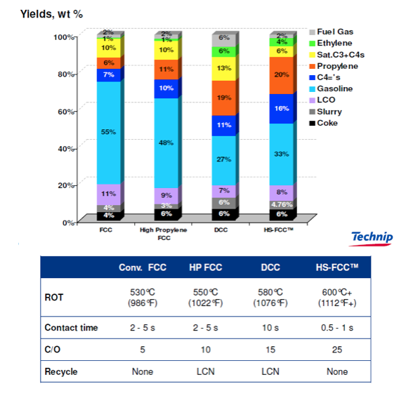
A higher reaction temperature (TRX) is observed and a cat/oil ratio five times higher when compared to the conventional process units and the petrochemical FCC (HS-FCC™), leading to a growth of the light olefins yield (Ethylene + Propylene + C4=’s) from 14% to 40%.
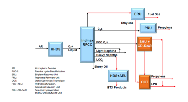
The installation of petrochemical catalytic cracking units requires a deep economic study taking into account the high capital investment and higher operational costs. However, some forecasts indicate growth of 4.0 % per year to the market of petrochemical intermediates until 2025. In this scenario the capital investment aiming to raise the market share in the petrochemical sector can be quite attractive, as it then allows a favorable competitive positioning to the refiner through the maximization of petrochemical intermediates. Figure 6 presents a block diagram showing a case study demonstrating how the petrochemical FCC unit, in this case the INDMAX™ technology by Lummus Company, can maximize the yield of petrochemicals in the refining hardware.
In refining hardware with conventional FCC units, further than the higher temperature and catalyst circulation rates, it’s possible to apply the addition of catalysts additives like the zeolitic material ZSM-5 that can raise the olefins yield close to 9.0% in some cases when compared with the original catalyst. This alternative raises the operational costs, however, as aforementioned it can be economically attractive considering the petrochemical market forecasts. Figure 7 presents some optimization strategies to improve the petrochemical yield in conventional FCC units.
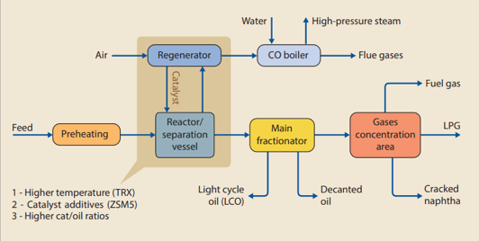
The use of FCC catalyst additives such as ZSM-5 can increase unit propylene production by up to 8.0%.
Installation of a catalyst cooler system raises the process unit profitability through the total conversion enhancement and selectivity to noblest products as propylene and naphtha against gases and coke production. The catalyst cooler is necessary when the unit is designed to operate under total combustion mode due to the higher heat release rate as presented below.
C + ½ O2 → CO (Partial Combustion) ΔH = – 27 kcal/mol
C + O2 → CO2 (Total Combustion) ΔH = – 94 kcal/mol
In this case, the temperature of the regeneration vessel can reach values close to 760 oC, leading to higher risks of catalyst damage which is minimized through catalyst cooler installation. The option by the total combustion mode needs to consider the refinery thermal balance, once, in this case, will not the possibility to produce steam in the CO boiler, furthermore, the higher temperature in the regenerator requires materials with noblest metallurgy, this significantly raises the installation costs of these units which can be prohibitive to some refiners with restricted capital access.
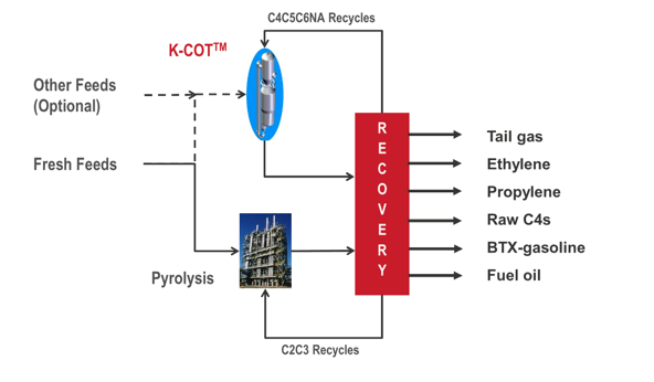
Among other petrochemical FCC technologies, it’s possible to mention the Maxofin™ and K-COT™ processes developed by KBR Company and the SCC™ technology developed by Lummus Company. Figure 8 presents a basic process arrangement for the K-COT™ technology developed by KBR Company.
Due to the higher production of light olefins, mainly ethylene, another important difference between conventional and petrochemical FCC units is related to the gas recovery section, while in conventional FCC is applied absorber columns, in petrochemical units is applied cryogenic processes though refrigeration cycles in similar conditions which are applied in steam cracking units, as presented in Figure 9 for the ACO™ technology developed by KBR Company.
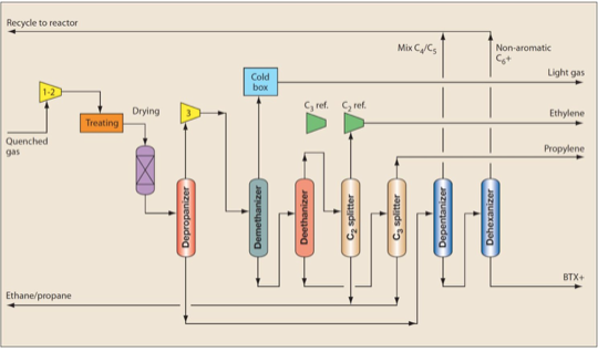
The cryogenic processes applied to olefins recovery raises, even more, the capital requirement to petrochemical FCC units when compared with conventional FCCs. Despite this, the growing market for petrochemicals and falling demand for transportation fuels tends to compensate for the higher investment.
Propylene Recovery Section
The growing demand by petrochemicals lead some refiners to install propylene recovery units aiming to allow the maximization of light olefins yield in refining hardware. Among the light olefins, propylene is one of the most relevant petrochemical intermediates due to the high demand and added value.
The propylene can be applied as an intermediate to the production in some fundamental products, for example:
- Acrylonitrile
- Propylene Oxide
- Cumene
- Acrylic Acid
- Polypropylene
Propylene can be produced through conventional processes like Steam Cracking and Fluid Catalytic Cracking (FCC) or through directed processes like metathesis of ethylene and butane, propane dehydrogenation, olefins cracking, Methanol to Olefins processes (MTO), among others. Currently a major part of the propylene market is supplied by steam cracking units, but close to 28% of the global propylene demand is from the separation of LPG produced in Fluid Catalytic Cracking Units (FCC).
Normally, the LPG produced in FCC units contain close to 30% of propylene and the added value of the propylene is close to 2.5 times that of the LPG. According to the local market, the installation of propylene separation units presents an attractive return over investment. Despite the advantage, a side effect of the propylene separation from LPG is that the fuel stays heavier, leading to specifications issues, mainly in colder regions. In these cases alternatives are to segregate the butanes and send this stream to the gasoline pool, add propane to the LPG or add LPG from natural gas. It’s important to consider that some of these alternatives reduce the LPG offer, which can be a severe restriction according to the market demand.
A great challenge in the propylene production process is the propane and propylene separation step. The separation is generally hard by simple distillation because the relative volatility between propylene and propane is close to 1.1. This fact generally leads to distillation columns with many equilibrium stages and high internal reflux flow rates.
There are two technologies normally employed in propylene-propane separation towers that are known as Heat-Pump and High-Pressure configurations.
The high-pressure technology applies a traditional separation process that uses a condenser with cooling water to promote the condensation of top products. In this case, it’s necessary to apply sufficient pressure to promote the condensation of products in the ambient temperature. Furthermore, the reboiler uses steam or another available hot source. The adoption of a high-pressure separation route requires a great availability of low-pressure steam in the refining hardware. In some cases this can be a restrictive characteristic and the heat pump configuration is more attractive, despite the higher capital requirements.
The application of heat pump technology allows a decrease of the operating pressure by close to 20 bar to 10 bar. This fact increases the relative volatility of propylene-propane, making the separation process easier and, consequently, reducing the number of equilibrium stages and internal reflux flow rate required for the separation.
Normally, when the separation process by distillation is hard (with relative volatilities lower than 1.5) the uses of heat pump technology are more attractive.
Furthermore, some variables need to be considered during the choice of the best technology for the propylene separation process, like availability of utilities, temperature gap in the column and installation cost.
Normally, the propylene is produced in the refineries to specifications. The polymer grade that is most common and has higher added value with a purity of 99.5 % (minimum) is directed to the polypropylene market. The chemical grade where the purity varies between 90 to 95% is normally directed to other uses. A complete process flow diagram for a typical propylene separation unit applying heat pump configuration is presented in Figure 10.
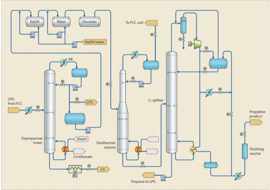
The LPG from FCC unit is pumped to a depropanizer column where the light fraction (essentially a mixture of propane and propylene) is recovered in the top of the column and sent to a deethanizer column while the bottom (butanes) is pumped to LPG or a gasoline pool, according to the refining configuration. The top stream of the deethanizer column (lighter fraction) is sent back to FCC where it is incorporated to the refinery fuel gas pool, or in some cases can be directed to petrochemical plants to recover the light olefins (mainly ethylene) present in the stream while the bottom of the deethanizer column is pumped to the C3 splitter column, where the separation of propane x propylene is carried out. The propane recovered in the bottom of the C3 splitter is sent to the LPG pool where the propylene is sent to the propylene storage park. The feed stream passes through a caustic wash treating aiming to remove some contaminants that can lead to deleterious effect to petrochemical processes. An example of is the carbonyl sulfide (COS) that can be produced in the FCC (through the reaction between CO and S in the Riser).
As aforementioned, facing the current trend of reduction in transportation fuels demand at the global level, the capacity of adding maximum value to crude oil can be a competitive differential to refiners. Due to the high capital investment needed for the implementation that allows the conventional refinery to achieve the maximization of chemicals, capital efficiency also becomes an extremely important factor in the current competitive scenario as well as the operational flexibility related to the processed crude oil slate.
Although there are advantages presented by closer integration between refining and petrochemical assets, it’s important to understand that the players of the downstream industry are facing a transitive period where, as presented in Figure 1, the transportation fuels are responsible for a great part of the revenues. In this business scenario, it’s necessary to define a transition strategy where the economic sustainability achieved by the current status (transportation fuels) needs to be invested to build the future (maximize petrochemicals). Keeping your eyes only in the future or only in the present can be a competitive mistake.
Deep Hydrocracking Technologies – Hydrogen Addition Route
Refiners processing heavy and extra-heavy (or high sulfur) crudes face a great challenge to meet the IMO 2020. Once it is extremely difficult to comply with the new regulation through carbon rejection technologies, in this case, the hydrogen addition technologies are fundamental.
The hydroprocessing of residual streams presents additional challenges when compared with the treating of lighter streams, mainly due to the higher contaminants content and residual carbon (RCR) related with the high concentration of resins and asphaltenes in the bottom barrel streams. Figure 11 shows a schematic diagram of the residue upgrading technologies applied according to the metals and asphaltenes content in the feed stream.
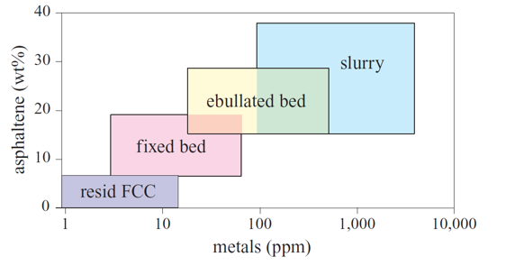
Higher metals and asphaltenes content lead to a quick deactivation of the catalysts through high coke deposition rate, catalytic matrix degradation by metals like nickel and vanadium or even by the plugging of catalyst pores produced by the adsorption of metals and high molecular weight molecules in the catalyst surface. Because of this, according to the content of asphaltenes and metals in the feed stream more versatile technologies are adopted aiming to ensure an adequate operational campaign and an effective treatment.
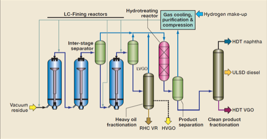
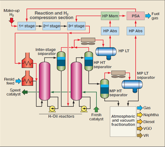
Despite the high performance, the fixed bed hydrocracking technologies cannot be economically effective to treat residue from heavy and extra-heavy due to the short operating lifecycle. Technologies that use ebullated bed reactors and continuum catalyst replacement allow higher campaign period and higher conversion rates. Among these technologies, the most known are the H-Oil and Hyvahl™ technologies developed by Axens Company, the LC-Fining Process by Chevron-Lummus, and the Hycon™ process by Shell Global Solutions. These reactors operate at temperatures above of 450 oC and pressures until 250 bar. Figure 12 presents a typical process flow diagram for a LC-Fining™ process unit, developed by Chevron Lummus Company while the H-Oil™ process by Axens Company is presented in Figure 13.
Catalysts applied in hydrocracking processes can be amorphous (alumina and silica-alumina) and crystalline (zeolites) and have bifunctional characteristics, once the cracking reactions (in the acid sites) and hydrogenation (in the metals sites) occurs simultaneously.
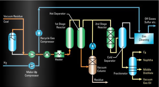
An improvement in relation of ebullated bed technologies is the slurry phase reactors, which can achieve conversions higher than 95%. In this case, the main available technologies are the HDH™ process (Hydrocracking-Distillation-Hydrotreatment), developed by PDVSA-Intevep, VEBA-Combicracking Process (VCC)™ commercialized by KBR Company, the EST™ process (Eni Slurry Technology) developed by Italian state oil company ENI, and the Uniflex™ technology developed by UOP Company. Figure 14 presents a basic process flow diagram for the VCC™ technology by KBR Company.
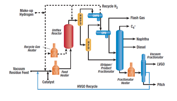
In the slurry phase hydrocracking units, the catalysts are injected with the feedstock and activated in situ while the reactions are carried out in slurry phase reactors, minimizing the reactivation issue, and ensuring higher conversions and operating lifecycle. Figure 15 presents a basic process flow diagram for the Uniflex™ slurry hydrocracking technology by UOP Company.
Other commercial technologies to slurry hydrocracking process are the LC-Slurry™ technology developed by Chevron Lummus Company and the Microcat-RC™ process by Exxon Mobil Company. Aiming to meet the new bunker quality requirements, noblest streams, normally directed to produce middle distillates can be applied to produce low sulfur fuel oil, this can lead to a shortage of intermediate streams to produce these derivatives, raising his prices. The market of high sulfur content fuel oil should strongly be reduced, due to the higher price gap when compared with diesel, production tends to be economically unattractive.
Petrochemical Integration – Strong Dependence of High Bottom Barrel Conversion
The focus of the closer integration between refining and petrochemical industries is to promote and seize the synergies existing in opportunities between both downstream sectors to generate value to the whole crude oil production chain. Table 1 presents the main characteristics of the refining and petrochemical industry and the synergies potential.

As aforementioned, the petrochemical industry has been growing at considerably higher rates when compared with the transportation fuels market in the last years. Additionally, it represents a nobler destiny and less environmentally aggressive to crude oil derivatives. The technological bases of the refining and petrochemical industries are similar which lead to possibilities of synergies capable of reducing operational costs and adding value to derivatives produced in the refineries.
Figure 16 presents a block diagram that shows some integration possibilities between refining processes and the petrochemical industry.
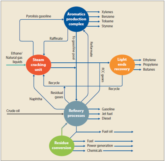
Process streams considered with low added value to refiners like fuel gas (C2) are attractive raw materials to the petrochemical industry, as well as streams considered residual to petrochemical industries (butanes, pyrolysis gasoline, and heavy aromatics) can be applied to refiners to produce high quality transportation fuels. This can help the refining industry meet the environmental and quality regulations of derivatives.
The integration potential and the synergy among the processes rely on the refining scheme adopted by the refinery and the consumer market. Process units such as Fluid Catalytic Cracking (FCC) and Catalytic Reforming can be optimized to produce petrochemical intermediates to the detriment of streams that will be incorporated into the fuel pool. In the case of FCC, installation of units dedicated to produce petrochemical intermediates, called petrochemical FCC, aims to reduce to the minimum the generation of streams to produce transportation fuels, however, the capital investment is high once the severity of the process requires the use of material with noblest metallurgical characteristics.
The IHS Markit Company proposed a classification of the petrochemical integration grades, as presented in Figure 17.
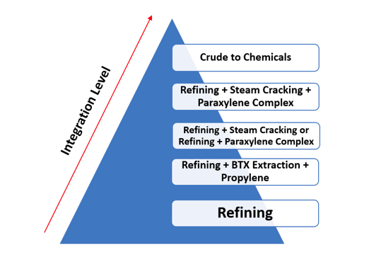
According to the classification proposed, the crude to chemicals refineries is considered the maximum level of petrochemical integration.
The Crude Oil to Chemicals – What is the Role of FCC and Hydrocracking?
Due to the increasing market and higher added value as well as the trend of reduction in transportation fuels demand, some refiners and technology developers have dedicated their efforts to develop crude to chemicals refining assets. One of the big players that have been invested in this alternative is the Saudi Aramco Company, the concept is based on the direct conversion of crude oil to petrochemical intermediates as presented in Figure 18.
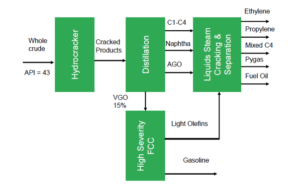
The process presented in Figure 18 is based on the quality of the crude oil and deep conversion technologies like High Severity or petrochemical FCC units and deep hydrocraking technologies. The processed crude oil is light with low residual carbon that is a common characteristic in the Middle East crude oils. The processing scheme involves a deep catalytic conversion process aiming to reach maximum conversion to light olefins. In this refining configuration, the combination of hydrocracking and petrochemical FCC is applied to ensure maximum added value to the processed crude oil through near zero production of transportation fuels. Figure 19 presents a comparison between the petrochemicals yields of traditional refineries, a benchmark integrated refinery and Hengli crude to chemicals complex, according to data from IHS markit.
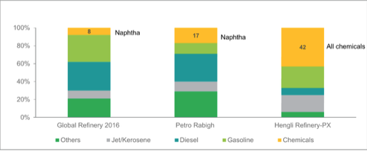
When analyzing Figure 19 it’s possible to note the higher added value reached in crude to chemicals refineries when compared even with highly integrated refineries.
Synergy between Hydrocracking and FCC Units – A High Bottom Barrel Conversion Refining Hardware
As aforementioned, sometimes the hydrocracking and FCC technologies are faced with competitor technologies in the refining hardware due to the similarities of feed streams that are processed in these units. In some refining schemes, the mild hydrocracking units can be applied as pretreatment step to FCC units, especially to bottom barrel streams with high metals content that are severe poison to FCC catalysts. Furthermore the mild hydrocracking process can reduce the residual carbon to the FCC feed, raising the performance of the FCC unit and improving the yield of light products like naphtha, LPG, and olefins. Figure 20 presents an example of high integrated refining configuration relying on hydrocracking and FCC technologies.
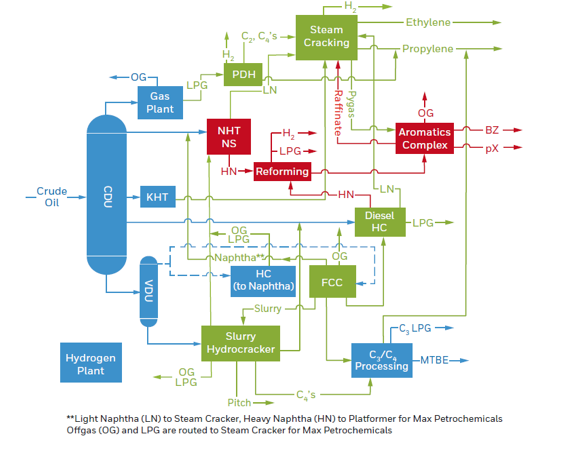
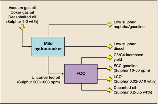
As presented in Figure 21, the integrated refining scheme relies on deep residue upgrading technologies as hydrocracking and fluid catalytic cracking (FCC) are capable of reaching the production of high-quality petrochemicals, according to the market trends. In some refining configurations, mild hydrocracking technologies are applied upstream of FCC units aiming to improve the quality of the FCC products, mainly the sulfur content. This processing configuration is exemplified in Figure 21.
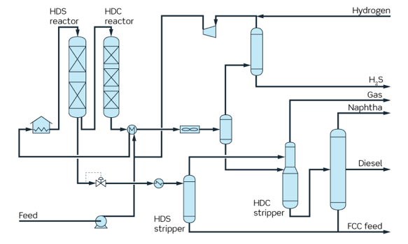
Examples of mild hydrocracking technologies are the IsoTherming™ process developed by the Dupont Company, and the SPC™ Process licensed by Haldor Topsoe Company, a simplified process flow diagram for SPC™ process is presented in Figure 22.
Considering the great flexibility of deep hydrocracking technologies that are capable to convert feed stream varying from gas oils to residue, an attractive alternative to improve the bottom barrel conversion capacity is to process in the hydrocracking units the uncracked residue in the FCC unit aiming to improve the yield of high added value derivatives in the refining hardware, mainly middle distillates like diesel and kerosene. This configuration can be especially attractive for gasoline Tier 3 production (with maximum 10 ppm sulfur) for refiners processing high sulfur crudes.
The Side Effect of Cracked Feeds – A Special Challenge to Hydrocracking Units
The most common cracked feeds directed to hydrocracking units are residual streams from FCC like Light Cycle (LCO) and Decanted Oil (DO) and Heavy Coker Gasoil (HCGO) from Delayed Coking units. Another less common feed is residue from Visbreaking units.
The main characteristics that influence in the hydrocracking performance for each feedstock is presented below:
- FCC Cycle Oils – Present high aromaticity that are normally refractory to cracking reactions as well as refractory sulfur components, raising the sulfur content in the final products and reduction in diesel cetane number, on the other side, normally presents low basic nitrogen content that is a poison to the hydrocracking catalysts.
- Thermal Cracking Feeds – Normally presents low aromatics content but concentrate refractory sulfur components.
The Heavy Coker Gasoil (HCGO) is an interesting case study as a feed to hycrocracking unit. Refiners with high complexity refining hardware can rely on the synergy between delayed coking and hydrocracking technologies to ensure added value to bottom barrel streams.
The quality of the HCGO relies on the quality of the feed to the delayed coking unit as well as the operating mode of the unit, mainly the recycle ratio. Higher recycle ratios produce better quality HCGO once reduced Conradson Carbon Residue (CCR), reducing the contaminants content like metals, sulfur, and nitrogen.
Despite this advantage, the delayed coking operators normally minimize the recycle ratio to minimum as possible aiming to raise the fresh feed processing capacity and the quality of HCGO is not an optimization focus of the refinery. For this reason, normally the HCGO is a hard feed to hydrocracking units due to the high content of refractory sulfur components, high CCR, high nitrogen content, and aromatics concentration.
The sulfur and nitrogen content raises the heat release in the first bed (Higher exothermal profile) that can produce damage to the catalysts, the nitrogen tends to inhibit the cracking reaction leading to lower conversion in the unit. Hydrocrackers processing feeds with high nitrogen content tend to apply processing configuration with intermediate gas separation to control the catalyst activity. The higher production of H2S and NH3 due to the higher concentration of sulfur and nitrogen reduces the hydrogen partial pressure, raises the necessity of wash water to the units, and can raise the corrosion rate in the processing unit.
Aromatics compounds tend to raise the hydrogen consumption, the heat release in the catalyst bed, and are precursors of coking deposition that deactivate the catalyst. Other side effects of the cracked feeds to hydrocracking units are the impact over the quality of the final products like lower cetane number of diesel, higher smoke point of kerosene, lower viscosity index in the lubricating oils and higher sulfur content.
As described above, processing cracked feeds in hydrocracking units present some additional challenges to refiners related to hydrogen consumption, better quench design of the catalyst bed due to the higher exothermic profile of the reactions, and lower global activity of the catalyst due to the higher poison content, like basic nitrogen. These characteristics lead the refiners processing cracked feeds in hydrocracking units to invest more capital in feed treating systems like filtering and guard beds, despite this apparent disadvantage, refiners able to add value to bottom barrel streams can enjoy a highly competitive advantage considering the downstream market post IMO 2020. For refiners processing extra-heavy bottom barrel streams, the deep hydrocracking technologies like slurry phase hydrocracking can be an interesting option, despite the high capital and operating costs.
Conclusion
The current scenario indicates a competitive advantage to refiners capable of maximizing the yield of petrochemicals in the refining hardware. Ensuring higher added value to the processed crude oils and the adequate synergy between refining technologies is a basic concept in the downstream sector and one of the first steps to define adequate refining configuration. The synergy between residue upgrading technologies is increasingly relevant to the refiners aiming to keep and improve the economic sustainability of the refiners, especially considering the downstream market post IMO 2020. Considering the limitations of FCC technology to treat heavier feed stocks, the synergy with hydrocracking and mild hydrocracking units can allow a higher level of bottom barrel conversion and maximum production of high added value derivatives. Despite the relatively high capital cost, the synergy between hydrocracking and FCC units are economically attractive to the refiners inserted in markets with higher demand by lighter derivatives, especially petrochemicals and middle distillates. Although there are benefits of petrochemical integration, it’s fundamental to consider the necessity to reach a circular economy in the downstream industry. To achieve this goal, the chemical recycling of plastics is essential. As presented above, there are promising technologies which can ensure the closing of the sustainability cycle of the petrochemical industry.

Dr. Marcio Wagner da Silva is Process Engineer and Stockpiling Manager on Crude Oil Refining Industry based in São José dos Campos, Brazil. Bachelor’s in chemical engineering from University of Maringa (UEM), Brazil and PhD. in Chemical Engineering from University of Campinas (UNICAMP), Brazil. Has extensive experience in research, design and construction to oil and gas industry including developing and coordinating projects to operational improvements and debottlenecking to bottom barrel units, moreover Dr. Marcio Wagner have MBA in Project Management from Federal University of Rio de Janeiro (UFRJ), in Digital Transformation at PUC/RS, and is certified in Business from Getulio Vargas Foundation (FGV). Connect with Dr. Wagner on LinkedIn
References
- Advances in Catalysis for Plastic Conversion to Hydrocarbons – The Catalyst Group (TCGR), 2021.
- CHANG, R.J. – Crude Oil to Chemicals – Industry Developments and Strategic Implications – Presented at Global Refining & Petrochemicals Congress (Houston, USA), 2018.
- Encyclopedia of Hydrocarbons (ENI), Volume II – Refining and Petrochemicals (2006).
- FRECON, J.; LE BARS, D.; RAULT, J. – Flexible Upgrading of Heavy Feedstocks. PTQ Magazine, 2019.
- GARY, J. H.; HANDWERK, G. E. Petroleum Refining – Technology and Economics.4th ed. Marcel Dekker., 2001.
- MALLER, A.; GBORDZOE, E. High Severity Fluidized Catalytic Cracking (HS-FCC™): From concept to commercialization – Technip Stone & Webster Technical Presentation to REFCOMM™, 2016.
- MUKHERJEE, U.; GILLIS, D. – Advances in Residue Hydrocracking. PTQ Magazine, 2018.
- ROBINSON, P.R.; HSU, C.S. Handbook of Petroleum Technology. 1st ed. Springer, 2017.
- SARIN, A.K. – Integrating Refinery with Petrochemicals: Advanced Technological Solutions for Synergy and Improved Profitability – Presented at Global Refining & Petrochemicals Congress (Mumbai, India), 2017.
- SILVA, M. W. – More Petrochemicals with Less Capital Spending. PTQ Magazine, 2020.
- SINGH, V.P. – KBR Olefins Technology Solutions- The Key is Flexibility. Technical Presentation KBR Company, 2018.
- SPEIGHT, J.G. Heavy and Extra-Heavy Oil Upgrading Technologies. 1st ed. Elsevier Press, 2013.
- TALLMAN, M. J.; ENG, C.; SUN, C.; PARK, D. S. – Naphtha Cracking for Light Olefins Production. PTQ Magazine, 2010.
- TYAS, A. – Diesel Hydrotreating and Mild Hydrocracking. PTQ Magazine, 2011.
- VU, T.; RITCHIE, J. Naphtha Complex Optimization for Petrochemical Production, UOP Company, 2019.
- ZHU, F.; HOEHN, R.; THAKKAR, V.; YUH, E. Hydroprocessing for Clean Energy – Design, Operation, and Optimization. 1st ed. Wiley Press, 2017.
This article has been reprinted from its original appearance on LinkedIn with the permission of the author.


Dear respected Dr.Wagnar ,
I have enjoyed the article , I’m operation engineer at FCC unit in KNPC Kuwait , Can filtered slurry oil from FCC bottom can be fed to HCR and what are the advantages and disadvantages of this modification on economical and enviromental scale foe both FCC & HCR units ?
I really liked your article it is considered as refernce and i would like to know what are the services that you can offer to enhance our refining industary performence.
Best Regards