The subject transformer is 1 MVA, 2400-480V, and was the sole power source for a small nitrogen plant within a refinery. Typical loading was less than 50% capacity. After two years of service the annual DGA sample indicated evidence of internal overheating and arcing. Two years was too long for ‘infant mortality’ and too short for age-related degradation.
The nitrogen plant was taken out of service long enough for the transformer to be de-energized, de-pressured, and inspected internally by a service contractor. The #1 suspect is generally the tap changer, and sure enough, they found a bad connection and a bolt that showed obvious evidence of overheating. The connection was cleaned, the bolt replaced, and the transformer closed up, purged, pressurized, and placed back into service. All seemed fine.
The next DGA a year later showed decreased levels of hydrogen (Partial Discharge indicator), but slightly higher levels of heat indicator gases and acetylene (indicating arcing). None of the levels were high enough to generate a lot of concern based on typical industry accepted standards, but the site Power Distribution personnel were suspicious of the trend, and especially the slight increase in acetylene. They brought a testing contractor on site who demonstrated a fairly new technology to detect and display PD and arcing under normal operating conditions in the field. Utilizing a High Frequency CT on the tank ground, the test equipment quickly identified what was believed to be internal arcing still occurring in the transformer, but the associated acoustic devices were unable to pinpoint the problem area.
The next opportunity to take the transformer out of service and perform an internal inspection was 2 months later. The original service contractor was called back on site and performed a thorough inspection using a borescope to get a look at every accessible area in the transformer. The two engineers performing the inspection each had over 20 years of experience with transformers. No problems were noted during the inspection, and the transformer was placed back into service.
At this time the manufacturer was brought into the discussion. They didn’t really have a large concern over the gas levels, and did not have any experience with the PD/Arcing test equipment. Based on their interpretation of the DGA and the PD/Arcing test results, the refinery Power Distribution group believed the transformer was in poor health and should be replaced. The manufacturer disagreed and concluded any further action would have to be the refinery’s responsibility.
A new transformer was ordered. DGA samples and PD monitoring were performed more frequently until the new unit was received and the Nitrogen plant could be taken down long enough to replace the transformer. Both the PD testing and the samples indicated the problem was still present.
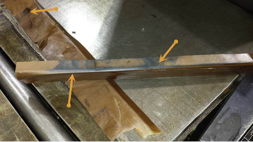
Once the transformer was removed from service, it was returned to the manufacturer for an autopsy. It was disassembled, and multiple locations of black soot and other indications of arcing were discovered involving the core and core insulation. It was determined that the core grounding method was causing differences of potential resulting in arcing. Repairs were made and the transformer was returned to the refinery as a spare.
In this case, the openness to utilize new technology and the persistence of the maintenance personnel to get it right resulted in the proper decision on a critical piece of equipment. Not as obvious but fundamentally just as important was the willingness of the refinery management to trust their on-site subject matter experts when the manufacturer was expressing an opposite viewpoint. This kind of culture is created over time, and is the product of dedication to developing a world class maintenance organization.
Exhibits
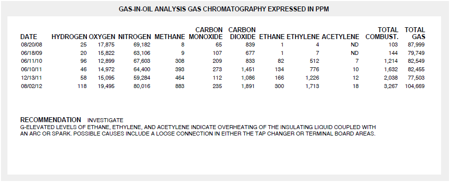
The oil analysis history shows a jump in 2010, two years after the initial installation. There was also an obvious increase at the 2012 reading.
Post-autopsy, the manufacturer concluded “The cause for elevated Gas levels appears to be high intensity current arcing because of high temperature thermal fault or vice-versa.”
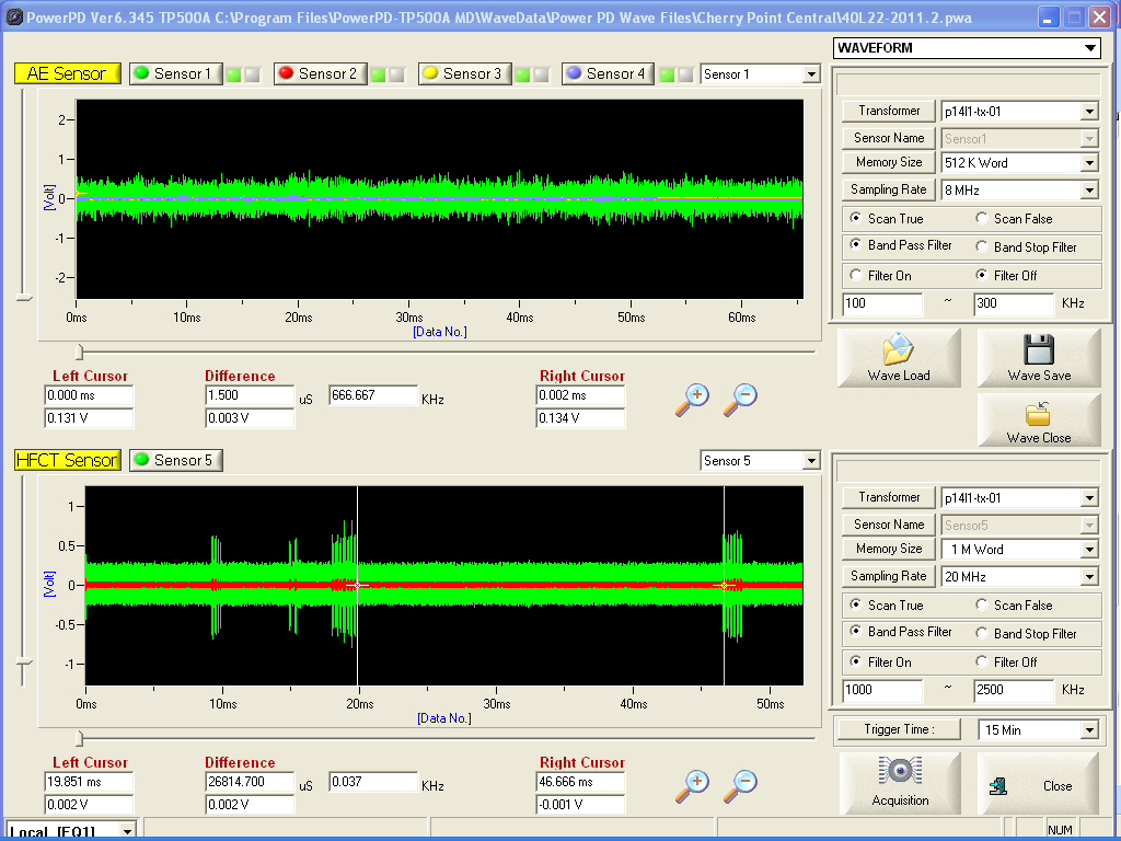
The location of the arcs, in multiple places between the core to core and core to frame , is hard to detect with acoustic sensors (upper display). The High Frequency Current Transformer (HFCT) clamped around the tank ground had no problem detecting the arcing waveform. This irregular pattern is evidence of arcing or sparking rather than Partial Discharge, which is repetitive every half cycle. The arcing was happening nearly continuously, and was detectable almost every time a sample was taken.
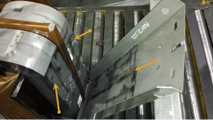
The factory performed a complete disassembly in order to identify the cause of the problem. They determined multiple core ground points created different potentials, resulting in arcing between the core and frame, and from core to core across its insulation.
Black marks from arcing between outer loop of core and inside segment of U-frame.
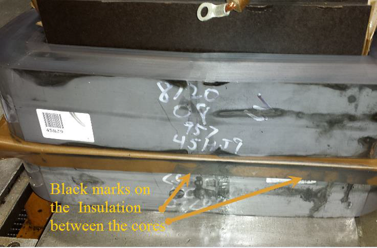
Black marks from arcing on the insulation between the cores
Black marks from arcing on the insulation paper between core loops


Leave a Reply