


History and Function
For nearly 100 years the lift and turn metal plug valves have been used in some of the most severe process applications. The unique and rugged design of the valves has enabled it to outlast many competing designs.
Originally developed for the FCC process as a catalyst withdrawal valve, the design incorporated the linear stroke of a common gate valve with the quarter turn motion ball valves or lubricated plug valves. The problems experienced by industrial manufactures of that era were not much different than what coker unit operations folks deal with today. The constant flow of particulate and abrasive material created issues for shut off and while lubricated plugs seem to handle this to some extent, the lubricant could not withstand the high heat and would dissipate, leaving the valve inoperable, or, in some instances the lubricant could be maintained with constant attention and re-filling of the valve but the lubricant would then begin to collect the particulate and thus, create the same issue of a valve that would simply not turn. Gates valves performed no better as the seating areas would be exposed to the process abrasion and the cavity in the bottom of the valve would fill and not allow for the valve to properly close.
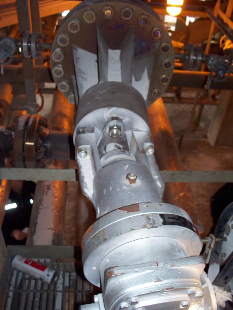
The operation of the valve is relatively simple and unique. The first motion of the valve is the lifting of the plug. Because of the taper design of the plug, as soon as it lifts, it loses contact with the body. This lift creates a shear effect and frees the plug. Now that the plug is in the lifted position it is free to move in a quarter turn motion without the damaging effects of metal on metal rubbing. The valve will rotate quarter until the plug port aligns with the waterway and now begins to descend back down into the seating area of the body. This downward force creates the wedging effect of the tapered plug into the corresponding body seats. The body of the valve does have void areas around the plug that are exposed to fowling during the cycle. The body will typically be fitted with purge piping for either steam or flush oil. These purge ports allow for this inert material to flow into the body during the cycle and prevent the collection of material in these areas around the plug. The purge media should be maintained at a higher pressure than the process media, thereby effecting a positive flow of purge into the body during the cycle this can also act as a positive displacement seal once the valve goes to the fully seated closed position.
For years the lift and turn metal seated plug valve was used with success on the feed lines to the drums at a major refinery located in the U.S. As the coker industry moved more and more to automation and the removal of company personnel from the units, reliability issues began to arise.
These once-trusted valves suddenly began creating reliability issues almost immediately. The automation (electric actuators) was the first sign of trouble. The torque switches started to trip, causing a stop in the movement of the valve. Typically, the instrument group would be called out to resolve this problem. The common fix for this recurring headache was often to increase the torque switch. This allowed more force to be applied to the gear/screw gear. In effect, this was only putting a bandaid on the situation rather than fixing it. The problem was still there; it was just further down the road.
Increasing the torque results in premature wear and tear of the screw gear, creating a lock-up of the screws and making the valve inoperable. Often, if the torque issue did not occur, differential pressures due to purge media or process would also create this lock-up of the screw gear, and again, make it impossible to achieve a smooth transition from drum to drum. These persistent problems and the need for maintenance by the instrument and operations personnel forced a change to a new technology.
A New Approach to An Age-Old Problem
The inception of the MIAM INNO-MAT gearing system occurred eight years ago as a viable option to the challenges posed by the traditional system. The effort was made to eliminate screws and indexing balls for the lift and turn motion. The INNO-MAT works with a set of three cylinders. The first, called a gear cylinder, is connected to a common manual gear operator I.E. auma / master gear / diamond gear. This gear cylinder has a large groove cut into it, very much like a chevron shape. Secondly, the stem cylinder, is connected to the stem of the valve. This cylinder has a large axle that looks somewhat like a train rail car axle. Thirdly, the stroke limiter or guide cylinder. This cylinder has a large groove cut into it that the stem cylinder axle rides on. The operation is rather basic. As the manual gear is turned the chevron groove that exist in the gear cylinder is turned. This turning motion and groove forces the stem cylinder axle to lift, in turn lifting the plug out of the seating area in the body. Once the plug is fully lifted, the angle of the groove will begin to force the stem cylinder axle to rotate quarter turn. This motion is a captured motion as stem cylinder axle will follow the track that is in the guide cylinder. Once this quarter turn motion is complete and the stem cylinder has contacted the edge of the guide cylinder the chevron groove of the gear cylinder will finish the motion by forcing the plug back down, completing the full cycle.
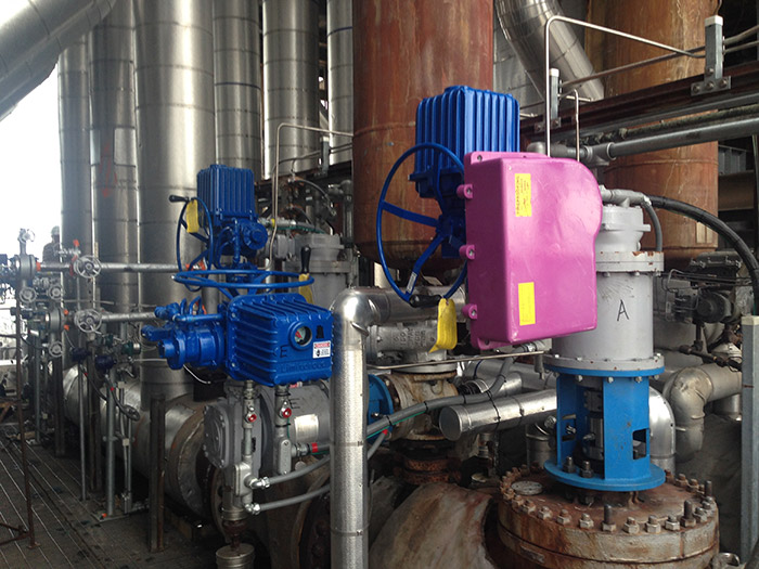
About four years ago MIAM was tasked by a major refinery client with installing the INNO-MAT gearing system on all four of the client’s drum feed line valves. They were located in pairs on both sides of the unit switch valve.
This fix immediately solved the valve problem for the client and the innomat devices have required no maintenance for any reason since installation. They continue to work to this day. These units were retrofitted on to the valves during their outage and had an approximate install time of three days in a shop setting.
MIAM will be exhibiting at RefComm® Galveston. Stop by booth #48 if you’d like to learn more about the innomat device and others.
To register for RefComm® Galveston, visit www.RefComm.com.
Photos courtesy of MIAM.

Leave a Reply