


Thank you to everyone who attended and contributed to the discussion with questions, poll feedback and comments. It was a truly interactive experience. We can only get better from here….. Here are some recaps and critical insights shared during the event.
With eREFCOMM, our goal is to recreate that community feeling of a live RefComm® event but in an online setting. Just like in the live RefComm events, the breakout sessions are ethereal and you have to be there to benefit from the information.
With that in mind, the event and the content of the material will not be reposted online. Instead, we are offering a summary of the event here for future reference. We hope that everyone will take advantage of attending the next eREFCOMM event, April 23, 2020 – Coke Drum Stripping Steam: A Goldilocks Approach.
The original topic was delayed coker coil outlet temperature (COT) and tube metal temperature (TMT). In light of the limited time, we elected to only cover one of the topics, TMT. Coil Outlet Temperature will be covered in a future eREFCOMM event – stay tuned.
The different types of TMTs were discussed. Installation type varies across the industry but most companies have standardized around the shielded type TMT. Generally, they are more reliable in the long term but are more expensive to install and can read slightly lower than unshielded designs. Industry studies show a 10-30F° (5-16C°) difference between the types but science is not definitive on either side of the argument….you decide. At Galveston 2021 RefComm, we hope to have some R&D data from a test furnace.
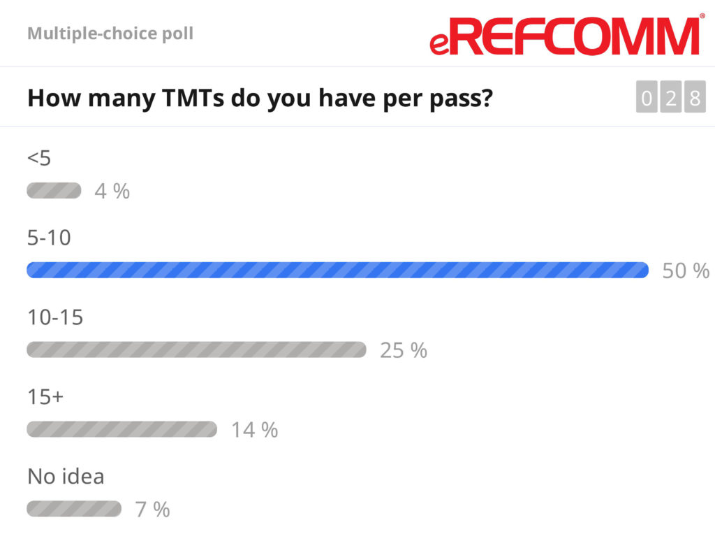
Older heaters may just have a few TMT’s per pass but new heaters can have 15 or more and the number of TMTs per pass has been increasing over time. According to our participant poll, the majority of respondents had 5-10 TMTs per pass. As TMT numbers are increased, we encourage operators not to focus the instruments in only the lower radiant section but the entire firebox for better insight into heater aging.
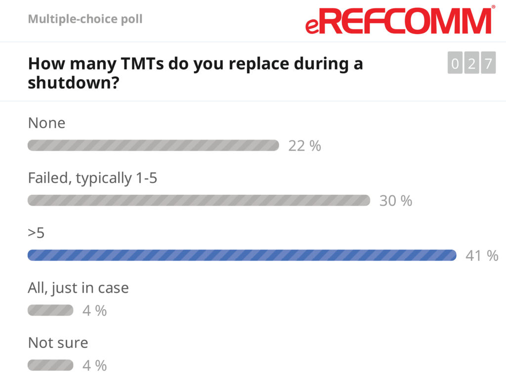
Regarding failure modes and installation errors, our next participant poll indicated that many sites are replacing greater than 5 TMTs each shutdown; therefore, failures are an ongoing problem for many operators. Vendors recommend that each TMT be replaced after 4-6 years in service. For many operators, this coincides with major turnarounds and could be planned accordingly. Alternatively, TAR time and labor are expensive. These TMTs could also be replaced during routine decokes at some other convenient time to save money.
According to Coking.com’s experience and the expertise of vendors, most of the issues with these TMTs can be attributed to issues during the design or installation of the mineral insulated (MI) cable. For single-fired heaters, the MI cable is recommended to be as short as possible from the fire box penetration, supported well, and strongly shielded from the fire (IR heat energy) by the tube. For double fired heaters, the MI cable penetration should be at the end of the fire box (near ubends) and run along the top of the tube for cooling (no gaps) with care taken at the tube supports.
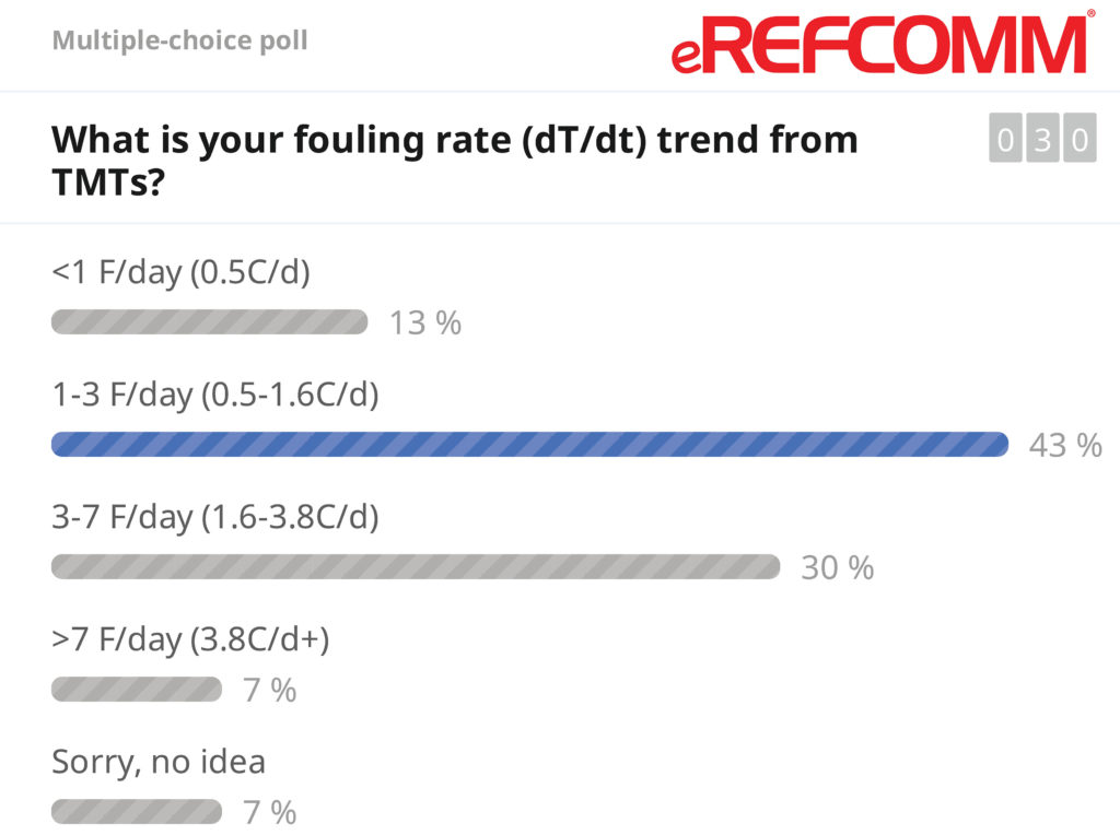
The next discussion, fouling rates and mechanisms that can impact TMT readings, focused on some of the causes of TMT rise and how to diagnose changes in the fouling rate. Most of the participants are seeing fouling rates around 1 – 3F°/day which is typical of the industry based on our experience. Some were better (lower) and others were significantly higher. Many factors are at play here from feed quality, heater design, and process conditions. Generally, most fouling occurs in the lower radiant section but a number of operators shared stories of fouling incidents in the upper radiant and convection section. Future eREFCOMM events will be dedicated to discussing fouling in more detail.
Accuracy of the TMTs and comparability of the readings compared to IR thermography was compared to an art to take the IR measurement properly. Some guidelines were discussed. A suggestion was made to do a baseline IR after a pigging or other offline decoke when the tubes are at their cleanest for an opportunity to get a TMT/IR comparison and define the proper settings in your IR camera for your heater.
Thank you to the vendors who provided some content for our presentation. More information can be found on their websites and YouTube channels. Some links are provided for your reference.
- Daily Thermetrics
- Daily Thermetrics-Tube Skin Temperature Monitoring PDF
- WIKA
- WIKI-Tubeskin Thermocouples Product Page
- WIKA – Installation of WIKA V-Pad Video
- WIKA – Installation for WIKA Refracto-Pad Video
We were not able to address all the questions in the session. Below are a few questions that were not addressed.
How do I know what the max tube metal temperature is for my heater?
The max allowable temperature is set during design. It is a function of the tube material, thickness, and pressure (max, often shut-in condition). For 9% Chrome (P9), the limit is commonly given as 1300F (704C). The limiting design parameter is commonly (not always) high temperature creep strength at end of run (EOR). API 530 design curves for allowable stress decrease very rapidly over 1300F for this material. Other materials are used in DCU fired heater service but are less common with other max allowable TMT at EOR
Please explain the impact of tightly adhered scale, along with underlying coking, on IR scans, and how to best asses the tube metal temperature in that situation.
Scale on the OD of the heater tubes presents many challenges for IR readings. Loose scale can read 20-50F hotter in some cases. Tightly adhered scale is more difficult to access because some cooling effects from the tube can be present. There is no rule of thumb to make this determination. The previous comment about a baseline IR is most relevant here to understand the difference between the TMT and IR in the unfouled condition. Unrelated to this current topic, cleaning of the OD of the tubes and OD coating have shown beneficial for evening out flux and in a few cases fouling. Cleaning your tube OD is something to consider if the scale is significant beyond just getting better IR readings.
Do you have any criteria to determine if the TMT is indicating a false value comparing with IR results?
Generally, when a TMT fails, it will change its reading very quickly. If the measurement drifts but moves directionally with the other process variables, one would be prudent to believe it in the absence of strong evidence to the contrary. Provided the camera settings, photo capture location/conditions, and tube scale are relatively constant, then comparing TMT/IR over time could provide some basis for which reading to believe. Generally, IR scans are recommended quarterly or more frequently depending on your fouling rate. Ideally, you have 2-4 scans over the run as the basis for trend/comparison when making the EOR determination and comparison of TMT/IR readings.