


Prepared By: Larry Ray, R&D Specialist, Isolation Valves, Flowserve
Gary Hager, R&D Engineer, Severe Service, Flowserve
CONTENTS
Introduction
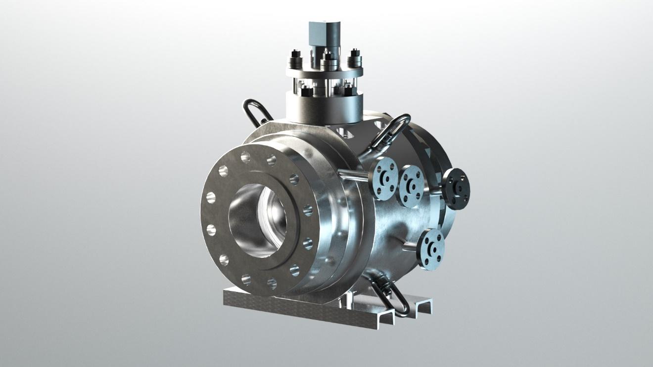
Severe service metal seated, floating ball valves, such as the Argus FK75F product line, are commonly installed in extremely harsh or severe service processes in petrochemical, mining, refining and power facilities. The severe service conditions these valves are exposed to can include, high temperatures, high pressures, abrasive, acidic and corrosive/erosive processes. Many times, these processes have an inherent nature to vary in composition and carry other process constituents in stream that lead to hangup, build up, agglomeration, coking, settling, chemical staining and deposition of unwanted process media in the spaces and cavities of an installed valve. To improve operation, reliability, and performance of these valves an integrated, cleaning or purging system has been identified as critical to many of the valves that are installed in these harsh or severe service processes.
The Challenge
The selection and configuration of a purging port and a purge system for a severe service metal seated, floating ball valve, such as the Argus FK75F, requires knowledge of the process and purging chemistry as well as experience with the specific purge media to be used as the feed stream, purge media pressure, temperature, flow rate, cycle frequency (intermittent or continuous), auxiliary purge media feed system(s), and purge media discharge management. Many considerations must be taken as well with purge sequencing across each purge port. The modes of purging and domain areas in the valve must be targeted, but an optimized purge system is detailed in Figure 1.
| Seat Cavity Purging | Body Cavity Purging | Downstream Purging |
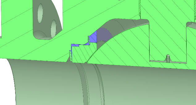 | 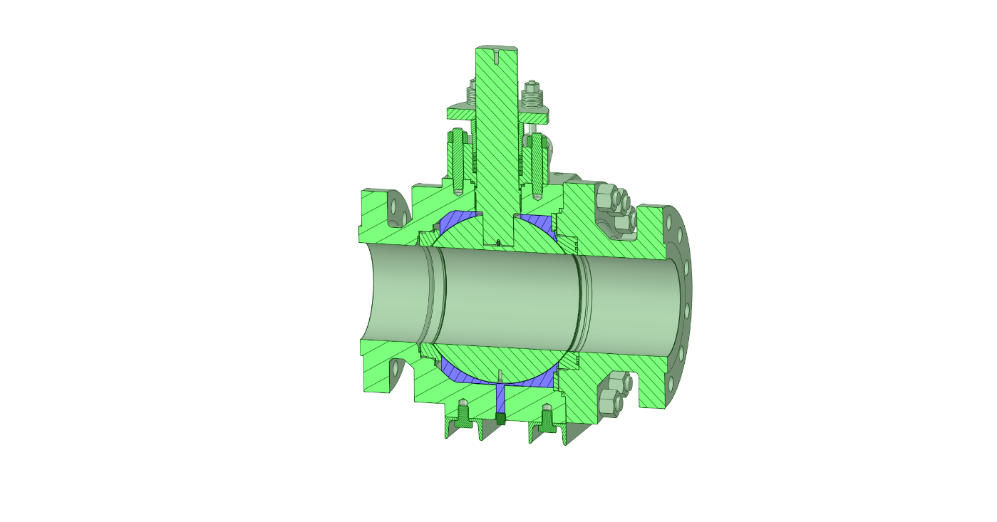 | 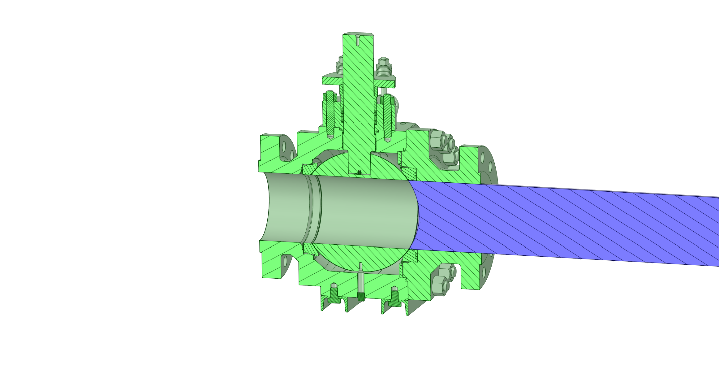 |
Figure 1: Argus FK75F Purging System Modes
With numerous valve sizes and pressure classes of metal seated, floating ball valves in the Argus FK75F lineup, there is variance in the purging port configurations and locations on the valve. Usage of technology and computer aid design and simulation software as well as validation tools is essential to designing an efficient, effective, reliable, and responsive purging system for these valves.
The Goal
To effectively design a purging system that will perform in the harshest conditions, various processes were evaluated in the analysis of design and optimization of the purge system. To achieve the best results in purge system behavior, the common physical states for purge media types are evaluated. Liquid and gas phase purge medias are evaluated and used in simulation, optimization, and validation of purge system design and operation. The primary objective of designing, optimizing, and validating the purge system is to ensure its effectiveness, efficiency, and the overall reduction in process media consumption through an improved, intermittent, purging system design.
Parameters
The process parameters identified for the purge system design and optimization are hydrocarbons and superheated steam. The process parameters of the feed stream through the valve to be purged has the characteristics of refining residue (resid) or bottom of the barrel process(s). Resid or residue is synonymous with severe service and in the section of the unit operations in this service, a valve can be exposed to high temperature, high pressure, high viscosity, coking, catalyst fines, solids, and other harsh elements.
Two purge media process types that are evaluated include vacuum gasoil (VGO) and superheated steam. Process parameters for the purge media types are made based upon residue or bottom of the barrel processing and conversion unit conditions from various plants.
Purge media inlet pressures at the valve were evaluated at 30 psi and 50 psi above the process stream pressure in the valve. Temperature was varied as part of the design and optimization efforts while maintaining the 30 psi and 50 psi differential pressure conditions. Upper and lower temperature limits were selected that would not adversely affect the mechanical strength or sealing integrity of the valve. Other process properties of the purge media were simulated and standardized based upon the pressures and temperatures selected of the purge media types, for the analysis.
Basis of Design
Historically, purge cycle frequency has been an intermittent or continuous purge operation for valves. Purging media is fed through multiple purge ports located strategically on the valve. Multiple purge ports result in effective cleaning of valve internal components when designed correctly. Purge port locations for the Argus FK75F were arbitrarily categorized, spatially chosen (shown in Figure 2) and validated with computational methods to verify the most optimal locations positions of the ports.
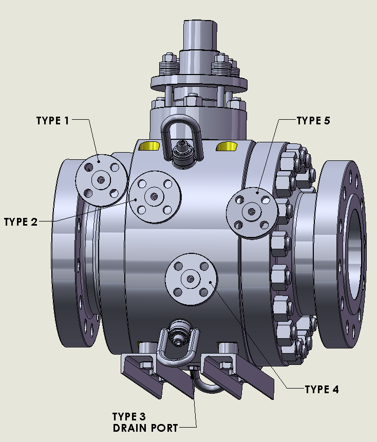 | 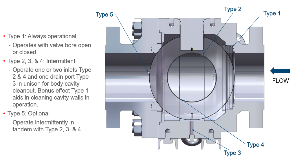 |
Figure 2: Argus FK75F Purge System Port Locations
The basis of design is to categorize purge port locations by purge types. Five purge ports were categorized by various purging or cleaning solutions for each mode of operation during a purging cycle. The categorized solution(s) per port are:
- Type 1 Purge designed to create positive pressure within the seat sealing area in between 2 spring disc. Spring discs designed as a pressure containing barrier without inversion or collapsing when the seat chamber is pressurized. Observation of spring disc will release pressure from seat chamber to body cavity chamber until equalization of pressure.
- Type 2 and 4 Purge designed to flush body cavity to exit thru type 3 drain port. Placement of ports type 2 and type 4 is an optimally defined geometry to maximize purge flow sweeping the body cavity. The combined synergy of 2 ports provides optimal volumetric cleanout of ball bore and the entire body cavity.
- Type 3 Purge drain port designed to facilitate purge type 2 and type 4 for maximum flow with minimal sonic choking to meet design requirements.
- Type 5 Purge type 5 is optional purge solution to flush behind the downstream seat bore and ball outer diameter or to connect to type 3 drain port for reclaiming process media.
Purge port types have various modes of operation. Each mode of operation is associated with position of the valve during purging cycle operations.
| Purge Port No. | Categorization | Mode of Operation | Valve Position |
| 1 | Type 1 | Continuous | Open or closed |
| 2 | Type 2 | Intermittent, with type 3 and type 4 | Closed |
| 3 | Type 3 | On/Off, sequenced with type 2 and/or type 4 in intermittent purge mode. | Closed |
| 4 | Type 4 | Intermittent, with type 2 and type 3 | Closed |
| 5 | Type 5 | Intermittent, with type, 2, 3, and 4 Continuous with type 3 for reclaiming process media | Open or closed |
Optimization
Computational fluid dynamics (CFD) is used to simulate purging system behavior within the valve spaces and cavities. Purge port geometry, valve process stream, and purge media parameters are entered into the simulation environment where iterations are completed utilizing several nodes and cores for computing. From the simulations the purge media flow could be characterized, visualized, and displayed for an analysis of flow, path line, wire draw, and other types of flow behavior during purging as shown in Figure 3.
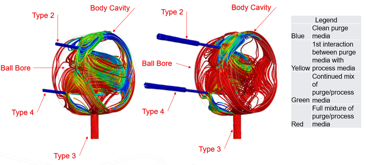
Figure 3: CFD Analysis Type 2 and Type 4. Varying domain inclusions at 5 sec
Experimental analysis criteria for each simulation is focused on length of a purge sequence, velocity of purge media, and purge media consumption. Optimization strategy for purge port location(s) is also a factor in the multi-iteration approach to design the most effective and efficient purging system for a metal seated floating ball. The process conditions of the test environment for the extensive CFD analysis are illustrated in Figure 4.
| Temperature | Pressure PSIG | Purge Media | Purge Seconds | Volumetric Cleanout |
| 850°F | 30,50 | VGO | 120 | 98% |
| 850°F | 20,40 | Steam | 120 | 98% |
Figure 4: Process Analysis requirements
Purge Port Types for Optimization
Type 1
Purge type 1 mode of operation is designed to be a pressure boundary barrier that prevents process media from entering. The seat freely floats to stay engaged with the ball for sealing purposes. Two spring discs are designed to not collapse under design pressure and designed to self-relieve the pressure into the body cavity until equalization of pressures occur. The seat boundary pressure zone is represented in blue below. Figure 5.
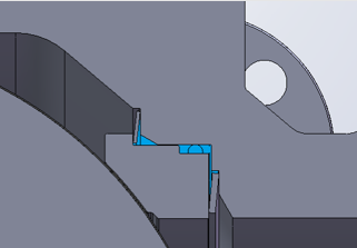
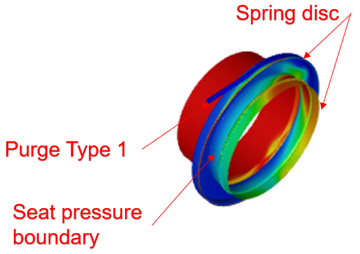
Figure 5 Seat geometry
Type 2 and Type 4
Purge port Type 2 and Type 4 are configured in a split flow design where port locations on the valve body are strategically located in accordance with best design practice sizing and position and verified with CFD tools to verify the positioning of the ports. Type 2 and Type 4 purge ports function as a split flow, simultaneous purging the system. Purge domain is represented in blue regions in Figure 6.
Figure 6: Type 2 and Type 4 Purge Domain
The purge ports create pressurized flow that sweeps through the ball bore while simultaneously along the ball outer diameter intersecting at the rear of the ball bore. The purge flow continues to sweep the body cavity exiting Type 3 purge port as shown in Figure 7.
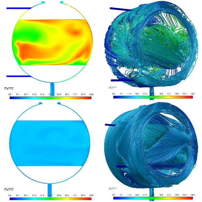
Figure 7: CFD Optimized Split Flow design with Type 2, Type 3, Type 4
Type 3
Type 3 purge port mode of operation is serving as a drain port for purge and process media that is consumed, cleaned, swept, and removed during purging operations of the valve.
An analysis was performed with CFD to demonstrate purge and process media discharge behavior and effects during purging operations. The analysis is to determine the maximum allowable differential pressure across Type 3 purge port before sonic choking or other cavitation effects develop and adversely affect Type 3 purge port discharge efficiency. Results of the analysis are graphically displayed in Figure 8.
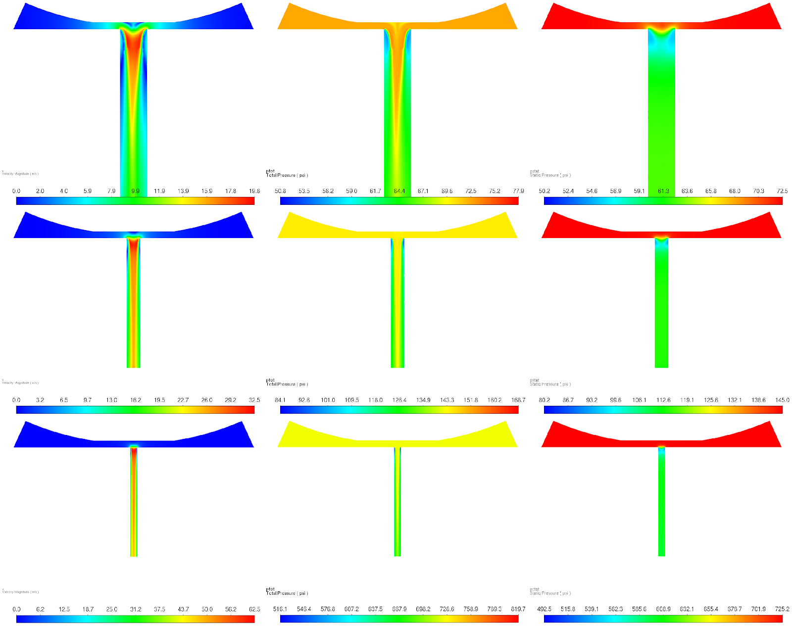
Figure 8: Sonic Choking Effects at Type 3 Purge Port
Type 5
Type 5 purge port (optional in some purging configurations) is positioned downstream of the ball within the connecting body of the valve. Like Type 1, 2, and 4 purge ports, design and CFD optimization define the most optimal position of Type 5 purge port, purge port size and entry angle. Type 5 purge domain is identified in Figure 9.
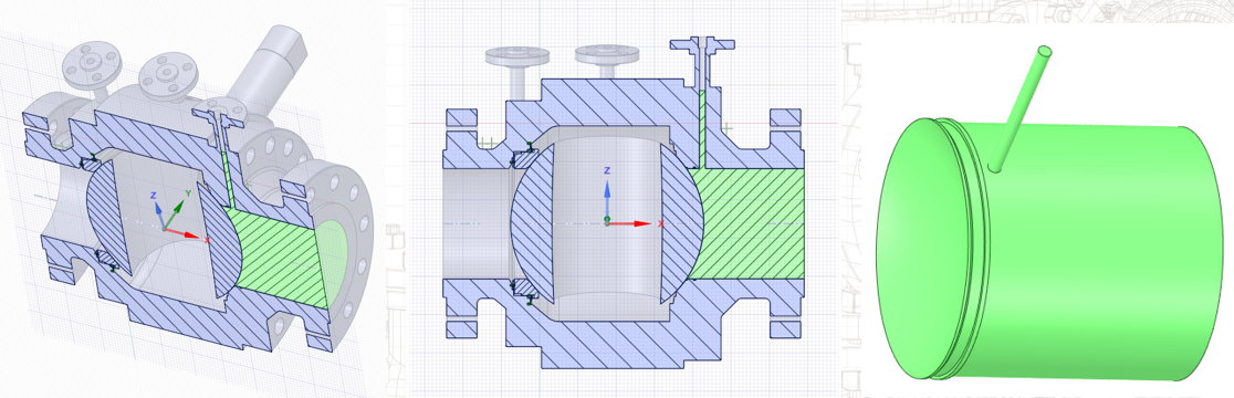
Figure 9: Type 5 Purge Domain
Type 5 purge port domain is optimized for maximum flushing behind the ball outer diameter and seat bore area including the valve body bore and adjacent, connecting pipeline(s). Type 5 port geometry sweeps the ball outer diameter and seat bore which will reduce valve operating torques before operation of ball valve. Figure 10
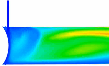
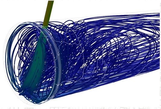
Figure 10: CFD Optimization of Type 5 Purge Port
Additional Considerations
Finite element analysis (FEA) is often used to evaluate the thermal and structural effects during purging of the valve. Derivations of these tools have also been developed to more quickly provide a purge feed stream set of inputs.
Consideration of a severe service ball valve installed in service conditions not conducive of having optimal purge media temperatures (cold purging) when in use was evaluated. Extreme temperature swings with cold purging will unload the body joint seals causing external body leaks to atmosphere. It’s imperative to access the optimal temperature range for purge media introduced into the valve process media stream.
Cold Purge Effects on Material Strength
To analyze effects of cold purging a twelve-inch, ANSI class 600, flanged ball valve was evaluated using FEA simulation. Specifications of the valve utilized in the case study is illustrated in Figure 11.
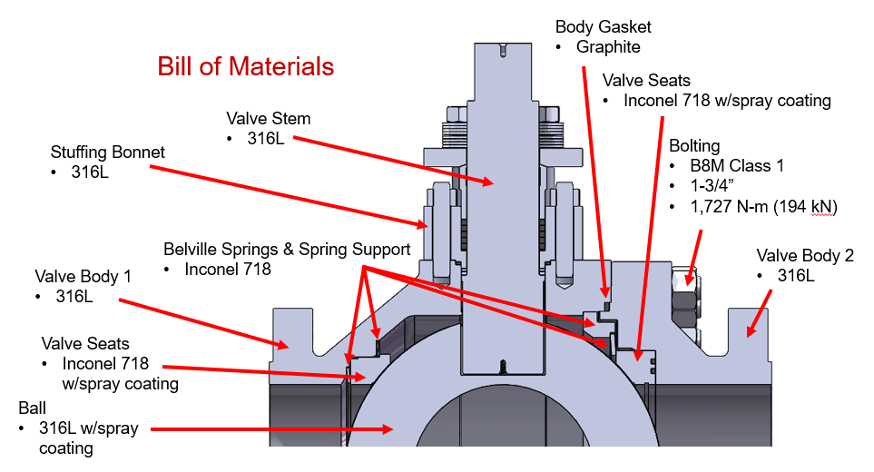
Figure 11: FEA valve material selection
The purpose of this evaluation is to baseline the valve geometry and material selection with elevated temperature to analyze the body gasket for any unloading. Unloading of the body joint seals would create a loss in sealing capacity. Once baseline is established, we move to introducing varying compression loads to evaluate the effects of unloading the body gasket seal. Figure 12
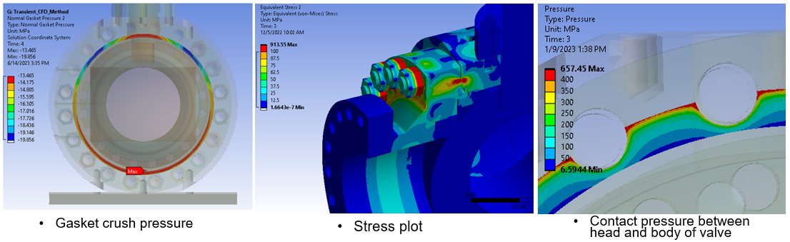
Figure 12: FEA analysis of gasket crush
Cold Purge Effects on Gaskets
An FEA study of gasket capabilities under varying compression loads when varying purge media temperatures through purge ports Type 2 and Type 4 and the valve body at 1100°F was completed. The purpose of this analysis is to determine the optimized temperature difference (ΔT) required to maintain proper gasket compression during intermittent purging cycles so to not exhibit body joint leaks to atmosphere.
Analysis was performed on an uninsulated valve with convection methodology. Coefficient of Thermal Expansion (CTE) values selected for the gasket material have a significant influence on the residual gasket crush at elevated temperatures. The relative effect of the purge vs the gasket crush over the purge cycle time of 120 second requirements pass the design criteria with no unloading of gasket value above the required gasket loading value. Figure 13.
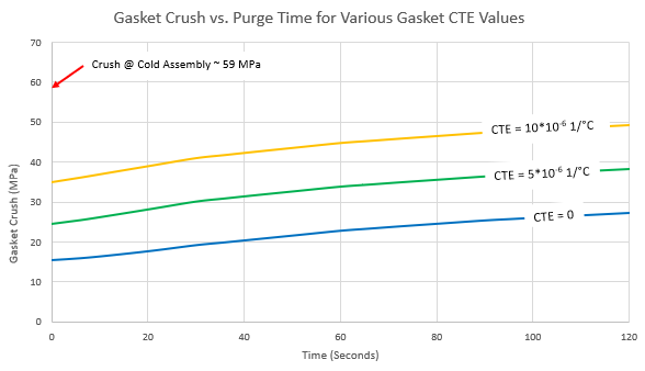
Figure 13: FEA Analysis of Gasket Crush vs Purge Time
An analysis of valve body gasket compression unloading due to cold purge effects indicated there is a 5% unloading of the gasket crush, in turn, resulting in a 75% loss of gasket load. With 15% unloading of gasket crush it was observed that there was a 95% loss of gasket load. These results of the analysis are shown in Figure 14.
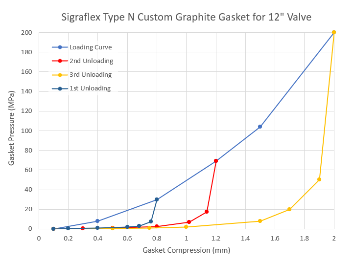
Figure 14: FEA Analysis Results of Valve Body Gasket Unloading
The FEA analysis for gasket unloading outputs with other critical data established the purge to process media differential temperature limitations on a body sealing joint. The recommended, maximum, differential temperature of purge to process media is 200 degrees Fahrenheit. This recommendation prevents cyclic compression and decompression of the body gasket. A summarized, graphical representation for the FEA analysis for differential temperature is shown in Figure 15.
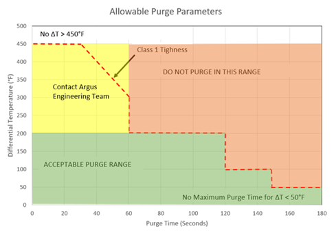
Figure 15: FEA Analysis Results of Purge to Process Differential Temperatures
Validation
In effort to validate all theoretical and optimized data, a validation test panel was designed, constructed, and utilized for testing.
The validation test panel is a process measurement tool that has been designed to validate the results of computational fluid dynamic (CFD) simulation analysis completed on the Argus FK75F metal seated floating ball valve purging system. The validation test panel is configured to utilize both water and compressed gas as purge media for validation testing.
Figure 16.
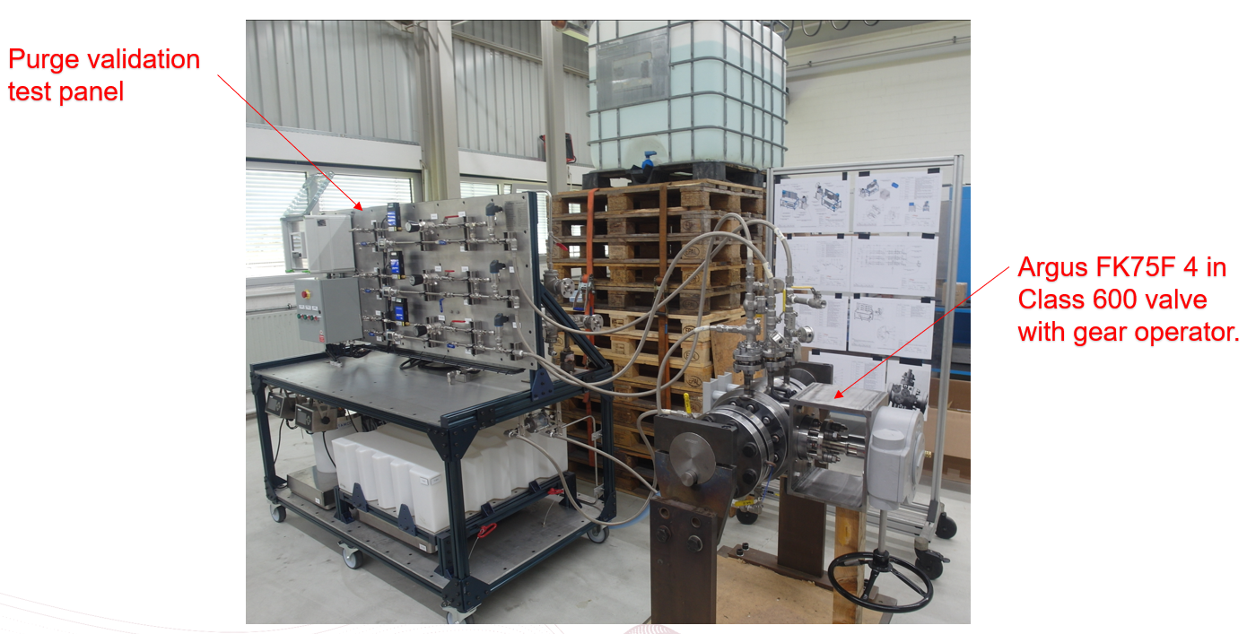
Figure 16: Validation Test Panel
Results
A creation of a purge port system design tool was developed from a combination of design, simulation, optimization, and validation efforts for the purge system on the metal seated floating ball valve.
The tool enhances end users’ ability to rapidly design, size, and utilize other customization efforts for incorporating a purging system on a metal seated floating ball valve in various applications. Input values such as valve size, pressure class, temperature, process media and purge media are entered into the valve purge system calculator (PSC) to retrieve statistical data such as purge volume flow rate, purge mass flow and purge volume flush times and apply into a purging system configuration that is considered “best fit” for the application. A snapshot of the user interface of this tool is represented in Figure 17.
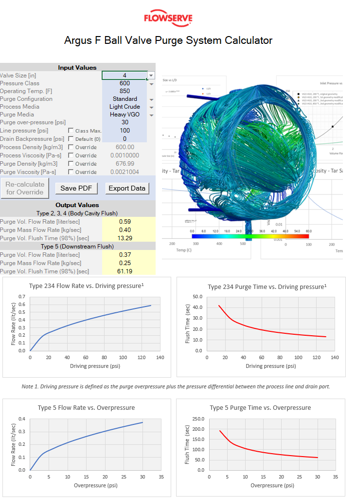
Figure 17: Purge System Calculator
Summary
The primary objective of designing, optimizing, and validating the purge system is to ensure its effectiveness, efficiency, and the overall reduction in process media consumption through an improved, intermittent, purging system design.
Intermittent purging is a necessary solution to address the challenges posed by extremely harsh or severe service processes in industries such as petrochemical, mining, refining, and power facilities. This enhanced purge solution will improve operation, reliability, and performance in valve designs installed in conditions that can lead to issues such as hangup, build up, agglomeration, coking, settling, and chemical staining.
The purging solution considers various operational parameters, including the availability and consumption of purge media used to flush the harsh process media. It provides a service that effectively flushes the valve cavity, ensuring it is prepared for the next operation. The purging solution benefits include a reduction in sticking or stalling of the valve in operations, a mechanism to prevent increased torques, or potential damage to the valve that would necessitate a redesigned valve or larger actuation on the current valve.
In conclusion, the design and implementation of an improved purge system offer significant benefits to the industry, including enhanced operational efficiency, increased reliability, and improved valve performance in challenging service conditions. By optimizing the intermittent purging process, it becomes possible to minimize process media consumption and ensure a more efficient and effective operation of valves in harsh environments.
Authors:


Editor’s Note: Flowserve has given Refining Community permission to reprint this article. The views, thoughts, and opinions expressed in the content above belong solely to the company/author and do not necessarily reflect the opinions and beliefs of Refining Community or its parent company, CRU Group.
Leave a Reply