


Operators had been struggling to know why their level indications on the Naptha Reformer splitter tower were so different from each other. They constantly experienced up to a 15 percent level indication offset between three different level transmitters. This had been going on for a few weeks after a turnaround, but there had not been a committed effort to find the answer. Overfilling this tower could result in an overpressure situation, and the new level instrumentation was safety critical. It was designed so any one of three independent level transmitters could be utilized as the process variable for the tower level controller.
Two of the three instruments were DP transmitters, one traced with steam and the other using electrical heat tracing. At that moment the steam traced DP transmitter ‘A’, was on control and indicating 50%, while the electrically heat traced DP transmitter ‘B’ showed 34% level. Level transmitter ‘C’, a guided wave radar, pretty much split the difference with a 43% level indication. The ambient temperature was about 50 deg F, or 10 deg C.
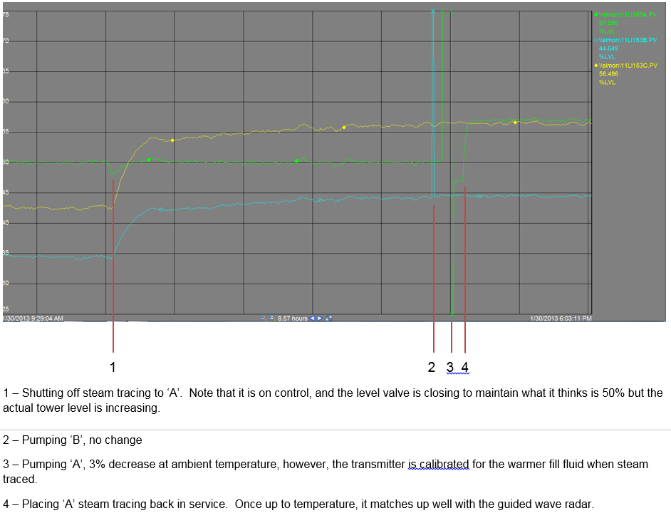
An experienced unit Instrument and Electrical (I&E) technician was asked to help sort out the problem, and after verifying the calibration on all three instruments began trending the levels. The tech then had the operators block in the steam tracing to the controlling transmitter ‘A’ while continuing to monitor trends. Almost immediately, the other two transmitters’ indications began to rise dramatically, leveling off somewhat after about 35 minutes, and then continuing to rise slowly over the next three hours. When the levels reached a steady state, ‘C’ (guided wave radar) read 57% and ‘B’ (electrically traced DP) read 44%. The difference between the two DP’s closed from 16% to 6%, while the guided wave went from -7% to +7% compared to ‘A’, and from +9% to +13% compared to ‘B’.
The next step by I&E was to have the operators change tower level control to the guided wave radar, and pump the legs on both DP transmitters with new fill fluid. While this didn’t change the level on ‘B’, the ‘A’ transmitter dropped to 47%. This left the difference between the two DP transmitters at only 3%. Shortly after pumping, I&E had the operators put the steam tracing back into service on ‘A’. Immediately its level indication began to climb until it nearly matched up with the guided wave radar, leveling off at 58%. There still remained the difference of the ‘B’ transmitter at 44%.
The I&E technician determined that the problem in this case was not instrument failure, calibration, placement, or with the control scheme. The problem was physics, specifically the changing gravity with temperature of the fill fluid of the DP transmitter legs. Changing fill fluid gravity acted no differently than changing the gravity in the tower. If you wanted both DP transmitters to read the same, they needed to have their process legs at the same temperature.
Although both transmitters were traced, steam tracing is not modulated; it is always on once placed into service. As long as the steam trap is functioning correctly, it should maintain a pretty steady temperature. Electrical heat tracing is different. It is usually turned on by a controller when the temperature falls below the setpoint, which in this case was set to about 40 deg F to prevent freezing. It was decided to replace the electrical heat tracing on the ‘B’ transmitter with steam tracing. Once accomplished, the three transmitters read within 1% of each other.
There is a fundamental lesson here for Operations. To be able to correctly and safely control their process, understanding the characteristics and details of their instrumentation is essential. The relationship between fill fluid temperature and level readings is not a hard concept to grasp, it just needs to be taught as part of an operator’s basic understanding of their instrumentation.
Author: Charlie Smith
Leave a Reply